

How To Draw A Gate On A Floor Plan
When you think of a floor plan, the first word that probably comes to mind is "blueprint." The two are related, but they're not exactly the same thing.
A floor plan is one of the construction drawings that you'll find included in a set of blueprints. They appear alongside site plans, elevation plans, and other detailed working drawings that offer builders a road map for how to build a structure. They serve as the fundamental kind of house plan for general contractors and others working in the construction industry.
But just what is a floor plan? And what do we need to know about its symbols?
A floor plan is a two-dimensional architectural drawing that shows the design of a house or other construction project from above. It is drawn in what's called a plan view, as if you're looking down through an invisible roof into the building.
Symbols on floor plans
A floor plan typically shows structural elements such as walls, doors, windows, and stairs, as well as mechanical equipment for the plumbing, HVAC, and electrical systems.
Floor plans use stylized symbols that often look like the outlines of elements they represent. Tubs, stoves, sinks, and stairs are familiar examples. These can appear along with built-in elements of interior design, like appliances, islands, cabinets, and bookshelves.
Objects and dimensions are also represented on a floor plan by solid lines or dotted lines of different weights and styles. For examples of the types of lines used on construction drawings, visit How to Read Construction Blueprints.
Floor plan symbols make up their own language, just as construction workers have their own vocabulary that they use to communicate when working on projects. Because it's essential for designers and builders to understand this language, a floor plan includes an important element called a legend, which acts as a key that helps viewers interpret the drawing.
The legend defines architectural symbols and notations on the plan. Many standard symbols appear there for specific projects. However, there can be variations in how symbols look and what they represent, which makes consulting the legend essential for each project.
For example, construction companies may use their own unique blueprint symbols in their set of drawings. Also, several different-looking symbols may represent the same item, depending on who you ask. Or one symbol may mean different things to workers with different specialties. Always search the legend on each unique plan to be clear about what the symbols mean.
Here are some common symbols you're likely to encounter in a floor plan.
Door, window, and stairs symbols

Doors and windows are elements found on every floor plan, and stairs are almost as common. Doors appear as gaps in a wall, often with an arc showing the way the door should swing. Windows are similar, appearing as narrow boxes in walls. Stairs are depicted most often as a series of rectangles.
Door symbols

Doors look like larger gaps between walls, often with a curved line to show which way the door will swing, indicating clearance. They may look different on floor plans depending on their form and function.
- For typical hinged doors that provide entry to a room, the curved line forms a quarter-circle (90-degree) arc.
- Double doors look like a stylized letter "M," with two curved lines meeting at the center.
- A bifold door, often used on a closet, is shown as being open: It looks like two peaked tents with a space between them, indicating where they'll meet when closed.
- A pocket door is a sliding door that mostly disappears into the wall when open. A standard sliding door is shown as a thinner line extending from a wider, dark rectangle.
Window symbols
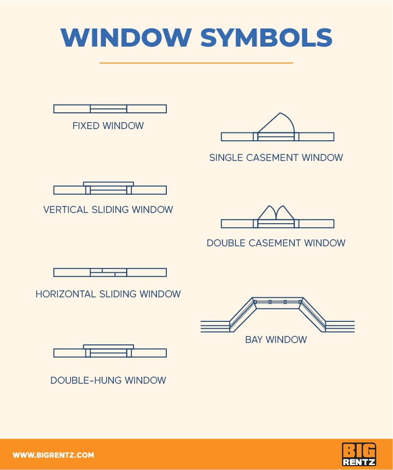
Windows are drawn as part of the walls.
- Regular sliding-glass windows are distinguished from solid walls by three parallel lines.
- Casement windows include arcs similar to those of doors, showing how they open outward.
- Bay windows are angled like the edge of a stop sign, breaking the straight-line trajectory of the wall.
Blueprints include a door and window schedule stating the style, size, and material of each.
Stairs symbols
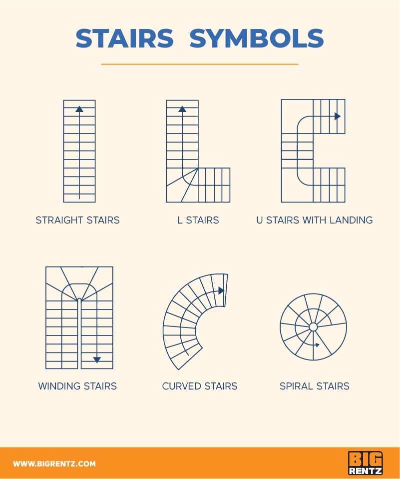
Like the rest of the plan, stairs are seen in a two-dimensional perspective from above. They look like a series of attached rectangles (usually) or other geometric forms.
- Some plans may show stairs bisected by a line with an arrow at one end to indicate which direction is up (ascending).
- Landings are shown as larger rectangles or squares.
- A curved or spiral staircase can look like part or all of a wagon wheel, with wedges joined around a curve.
Appliance and plumbing symbols
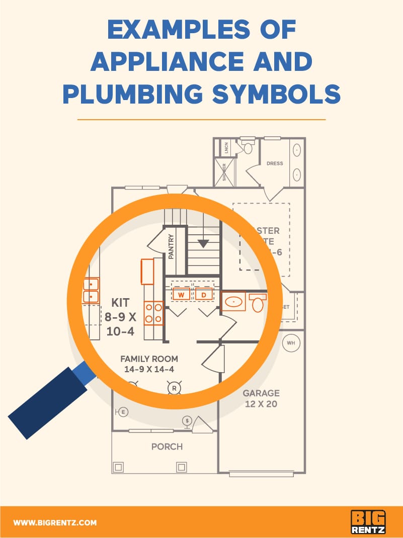
In floor plans depicting kitchens, bathrooms, and laundry rooms, you'll see symbols for appliances like the refrigerator, stove, washer, and dryer. These usually appear near plumbing elements like sinks, showers, toilets, and drains. Symbols can be accompanied by labels or abbreviations that further explain their functions, or not.
Appliance symbols
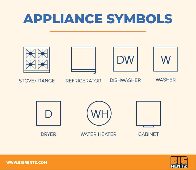
Stylized representations of built-in appliances such as refrigerators and stove-top burners are typically included in floor plans.
Simple outlines of appliances with specific hookup sites, such as a washer or dryer, are also included. Many are rectangles that surround a letter or two indicating their function (such as DW for a dishwasher; see list of abbreviations below).
Plumbing symbols

Common plumbing fixtures depicted in floor plans include a toilet, bathtub, and shower, along with different kinds of sinks: a freestanding sink, single vanity sink, double sink, cabinet sink, kitchen sink, laundry basin, etc.
Less common fixtures include a bidet or urinal. Associated bathroom features also may be depicted, including towel racks and toilet paper dispensers.
HVAC and electrical symbols

Since they lie largely inside a building's walls, infrastructure elements of the heating, ventilation, and air conditioning (HVAC) systems may be depicted on their own designated sheets within the set of blueprints. Symbols for parts located in the living space or outside the building, such as vents or the AC unit, are often included in the overall floor plan.
Similarly, symbols for internal electrical wiring and mechanisms can require their own complicated sheets in a set of blueprints. But outlets, switches, built-in lights, and other controls accessed in the living space usually appear on the overall floor plan.
HVAC symbols

The HVAC system may be illustrated by symbols for air conditioning units, furnaces, wall vents, ceiling vents, and other ventilation elements. Other HVAC equipment you might find on a floor plan include a pump, heater, return air vent, fan, straight duct, condenser, and Y junction duct.
A heating subcontractor might provide a separate duct and register layout for the HVAC system.
Electrical symbols

You may find a whole host of electrical symbols on a floor plan, showing wall jacks, TV and switch outlets, thermostats, garbage disposals, and more. Others include ceiling fans and lights, and floor outlets.
Electrical symbols often feature a subscript — small writing at the bottom of the symbol — that helps explain the outlet's function or rating. If you see a symbol with a subscript, it should be explained somewhere in the blueprint's legend. (For more information on abbreviations, see the section below.)
Wall symbols
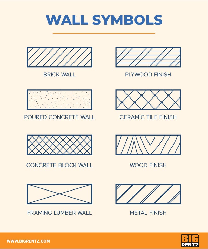
Walls are the most common elements of a floor plan. Thicker lines represent exterior walls, and thinner lines show interior walls. Sometimes there's no visible difference between them. Exterior walls also can be depicted by a black outline or double lines rather than a single, solid line.
Different materials may be represented differently on some plans. Walls may be drawn with hatching or other patterns inside to show whether they're made of brick, concrete, or framing lumber, for example. Outer materials or "finishes" also can be shown in this manner, including metal, hardwood, plywood, or ceramic tile.
Floor plan abbreviations
In addition to symbols, floor plans contain abbreviations for different elements and materials. These abbreviations can include (but are not limited to) the following:
- AC or A/C — Air Conditioner
- B — Basin
- BC — Bookcase
- BV — Butterfly valve
- CAB — Cabinet
- CBD — Cupboard
- CF — Concrete floor
- CL — Closet
- CLG — Ceiling
- COL — Column
- CW — Cavity wall
- CT — Ceramic tile
- D — Door or dryer
- DS — Downspout
- DW — Dishwasher
- EF — Exhaust fan
- FD — Floor drain
- GM — Gas meter
- HTR — Heater
- HW — Hot water unit or tank
- KIT — Kitchen
- LIN — Linen cupboard
- LTG — Lighting
- MSB — Master switchboard
- O or OV — Oven
- REFRIG or REF — Refrigerator
- SD — Smoke detector, sliding door, or sewer drain
- SHR — Shower
- WC — Toilet (water closet)
- VENT — Ventilator
- VP — Vent pipe
- WIC — Walk-in closet
- W — Window or washer
- WD — Window
- WH — Water heater
- WR — Wardrobe
Deciphering the scale on a floor plan

Blueprints for a new home are commonly shown on paper that measures 18×24 or 24×36 inches. Since floor plans need to fit on a sheet of paper, the drawings must naturally be much smaller than the completed project will be.
The scale of a project refers to how the measurements on the floor plans relate to the project's measurements once it's done. It is usually found in or near the title block, along with a compass showing the orientation of the home or structure on the building site. (Unlike on maps, the north arrow does not always point toward the top of the page, as the front of the structure may face in a different direction.)
Floor plans are most commonly (though not always) drawn on a 1/4" scale, which means a quarter-inch on the plan equals 1 foot of actual length on the completed structure. Some scales use metric instead of imperial measurements.
The scale ensures consistency and helps guarantee that the finished project will look the way it was intended — and that it will be structurally sound. The scale applies not just to the exterior walls, but to all elements of the floor plan.
Creating your own floor plans
Floor plans for a long time were drawn by hand, and some still are. If you're interested in creating a floor plan this way, you'll need the right equipment: drafting tools such as scales, compasses, drawing triangles, protractors, and templates.
But these days, home plans are most often produced digitally. You may need computer-assisted design (CAD) software and, to create prototypes, a 3-D printer.
Software programs such as Microsoft Visio and Floor Plan Creator have templates to get you started drafting your dream home. Some provide tutorials to help you learn home design and floor plan design, and some even offer options for free downloads.
Conclusion
Floor plans are like treasure maps drawn by architects and engineers to serve as guides for construction workers — only the landmarks are different. Instead of mountains and rivers, you see walls and doorways. Instead of cities and towns, you see stoves and tubs.
There's no single "X" that marks the spot where buried treasure lies in a floor plan. But if you follow the template, you'll wind up where you want to be: with a completed building that's not just structurally sound and functional but also comfortable and appealing.
Related Posts
How To Draw A Gate On A Floor Plan
Source: https://www.bigrentz.com/blog/floor-plan-symbols
Posted by: dollarsedid1987.blogspot.com
0 Response to "How To Draw A Gate On A Floor Plan"
Post a Comment